
Progress on NASA's Constellation
NASA's Constellation program, established in 2005, continues its work toward the building the future of manned space exploration in the U.S. The first test flight of the Ares I-X rocket - a functional mockup of the actual Ares I rocket, similar in shape and mass - is scheduled for July, 2009. The stimulus bill just passed by the U.S. Congress will be sending an additional $1 billion to NASA, $400 million of which is for its manned space program. Engineers are now busy refitting old facilities, running tests, building the infrastructure and working towards a planned first launch of a crew to the International Space Station in 2014. Collected here are photographs of various parts of the Constellation program coming together, including parts of the Orion crew vehicle, the Ares I and Ares V rockets, and supporting systems. (31 photos total)
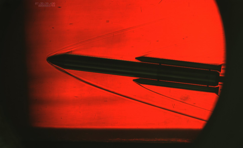
This schlieren photo from October 28th, 2008 depicts a wind tunnel test demonstrating air flow over the 0.34 percent scale model of the Ares V heavy cargo launch vehicle at Mach 4.5. Schlieren imaging is a diagnostic method used to visualize air flows with varying densities, widely used in aeronautical engineering to photograph the flow of air around objects. (NASA/MSFC)
2
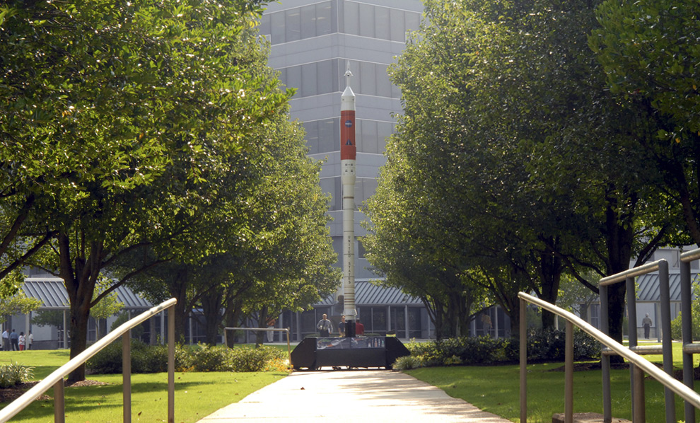
A scale model of the Ares I crew launch vehicle, for which NASA is designing, testing and evaluating hardware and related systems, is seen here on display at the Marshall Space Fight Center (MSFC), in Huntsville, Alabama on July 14th, 2006. (NASA/MSFC) #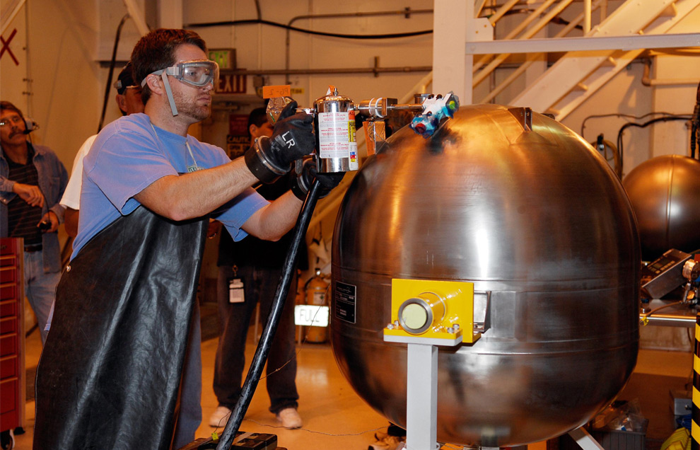
3
In the hypergolic maintenance facility at NASA's Kennedy Space Center, a technician adjusts equipment during testing of the Ares I-X Roll Control System, or RoCS. The RoCS Servicing Simulation Test is to gather data that will be used to help certify the ground support equipment design and validate the servicing requirements and processes. In an effort to reduce costs and meet the schedule, most of the ground support equipment that will be used for the RoCS servicing is of space shuttle heritage. This high-fidelity servicing simulation will provide confidence that servicing requirements can be met with the heritage system.(NASA/Kim Shiflett) #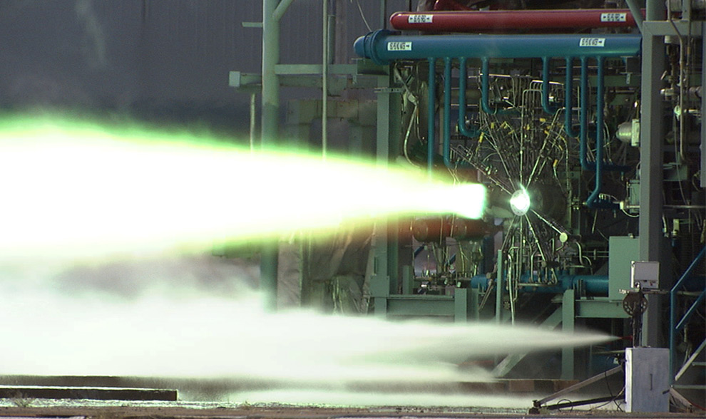
4
The Ares I launch vehicle's first stage is a single, five-segment reusable solid rocket booster derived from the Space Shuttle Program's reusable solid rocket motor that burns a specially formulated and shaped solid propellant called polybutadiene acrylonitrile (PBAN). The second or upper stage will be propelled by a J-2X main engine fueled with liquid oxygen and liquid hydrogen. This HD video image depicts a test firing of a 40k subscale J2X injector at MSFC's test stand 115 on September 9th, 2007. #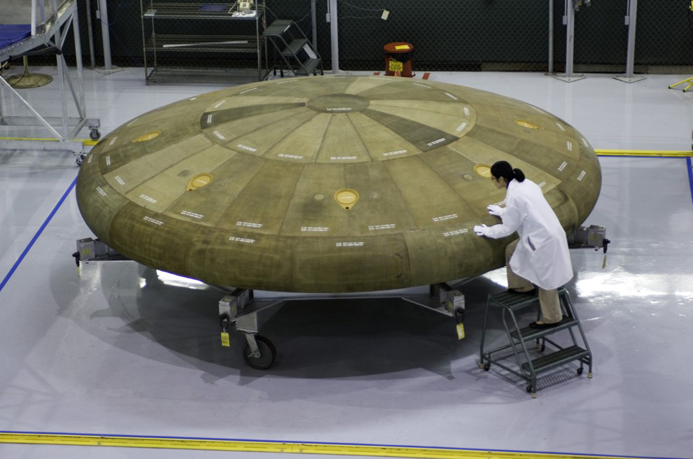
5
Boeing Advanced Network and Space Systems material and process engineer Elizabeth Chu inspects the Thermal Protection System Manufacturing Demonstration Unit developed for NASA's Orion Crew Exploration Vehicle project on November 13th, 2007. Boeing Advanced Systems was awarded a contract to develop a prototype heat shield to protect NASA astronauts from extreme heat during re-entry into the Earth's atmosphere upon returning from lunar and low-Earth orbit missions. (Boeing Photo - Joe Olmos) #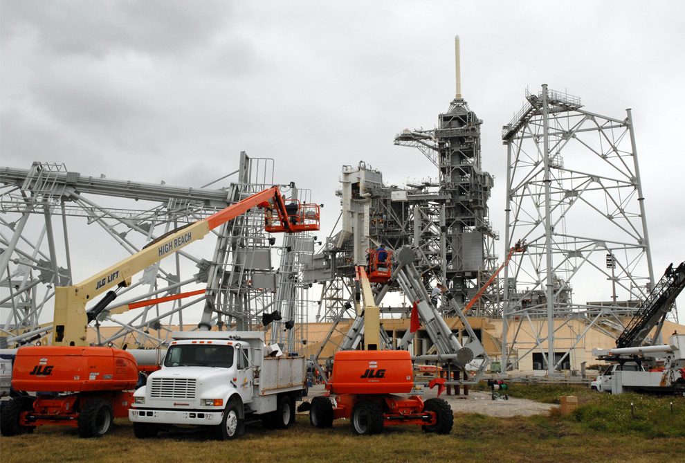
6
On Launch Pad 39B at NASA's Kennedy Space Center in Florida, equipment is set up to continue erecting new lightning towers on November 25th, 2008. Each of the three lightning towers will be 500 feet tall with an additional 100-foot fiberglass mast atop supporting a wire catenary system. This improved lightning protection system allows for the taller height of the Ares I compared to the space shuttle. Pad B will be the site of the first Ares vehicle launch. (NASA/Tim Jacobs) #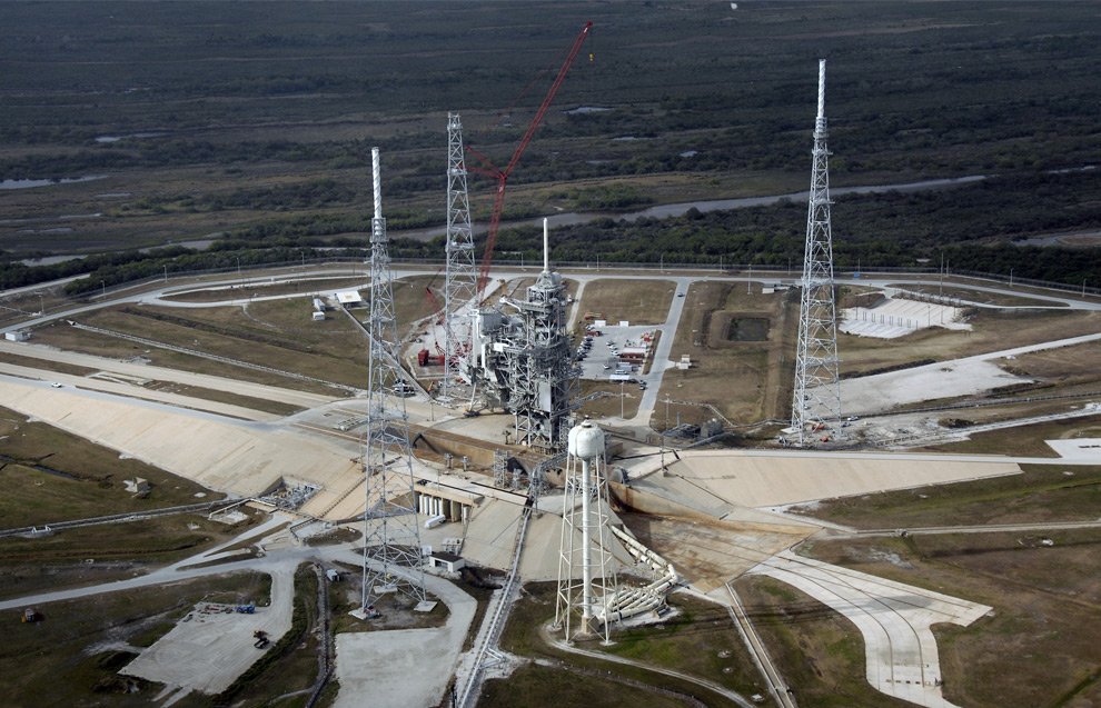
7
An aerial view of the newly erected lightning towers on Launch Pad 39B at NASA's Kennedy Space Center in Florida. The two towers at left and right contain the lightning mast on top; the one at center does not. At center are the fixed and rotating service structures that have previously served the Space Shuttle Program. In the foreground is the tower that holds 300,000 gallons of water used for sound suppression during a shuttle liftoff. (NASA/Kim Shiflett) #
8
Fog blankets the woods near a road in the Merritt Island National Wildlife Refuge at NASA's Kennedy Space Center in Florida. The center shares a boundary with the refuge that includes salt-water estuaries, brackish marshes, hardwood hammocks and pine flatwoods. (NASA/Jack Pfaller) #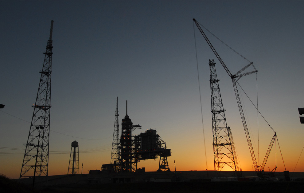
9
The dawn sky over NASA's Kennedy Space Center reveals the newly erected lightning towers on Launch Pad 39B. (NASA/Tim Jacobs) #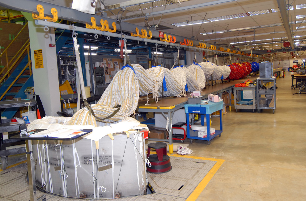
10
In the Parachute Refurbishment Facility at NASA's Kennedy Space Center, the process of packing a colorful main parachute, slated for use on the Ares I-X test flight, is under way. The new parachutes are red, white and blue. The launch is targeted for July 2009 from Kennedy Space Center's Launch Pad 39B and will provide an early opportunity to test and prove hardware, facilities and ground operations associated with the Ares I rocket. (NASA/Jack Pfaller) #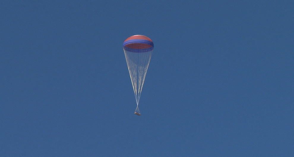
11
In this HD video image, the first stage reentry parachute drop test is conducted at the Yuma, Arizona proving ground on September 9th, 2007. The parachute tests demonstrated a three-stage deployment sequence that included the use of an Orbiter drag chute to properly stage the unfurling of the main chute. The parachute recovery system for Orion will be similar to the system used for Apollo command module landings and include two drogue, three pilot, and three main parachutes. (NASA/MSFC) #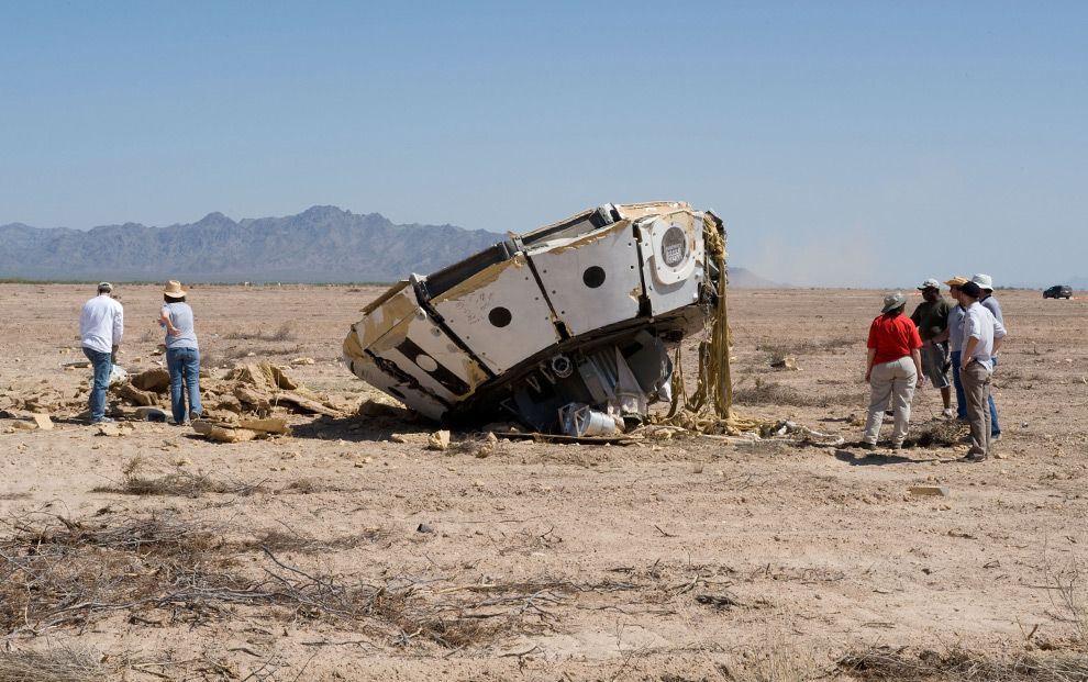
12
The mock-up of the Orion crew capsule used during the test of the parachute system for the recovery system of the Orion spacecraft on July 31, 2008 was severely damaged when a test set-up chute failed to properly inflate and caused the parachute system to fail. The failed parachute - called a programmer chute - was supposed to get the test vehicle set up to the correct test conditions. (NASA) #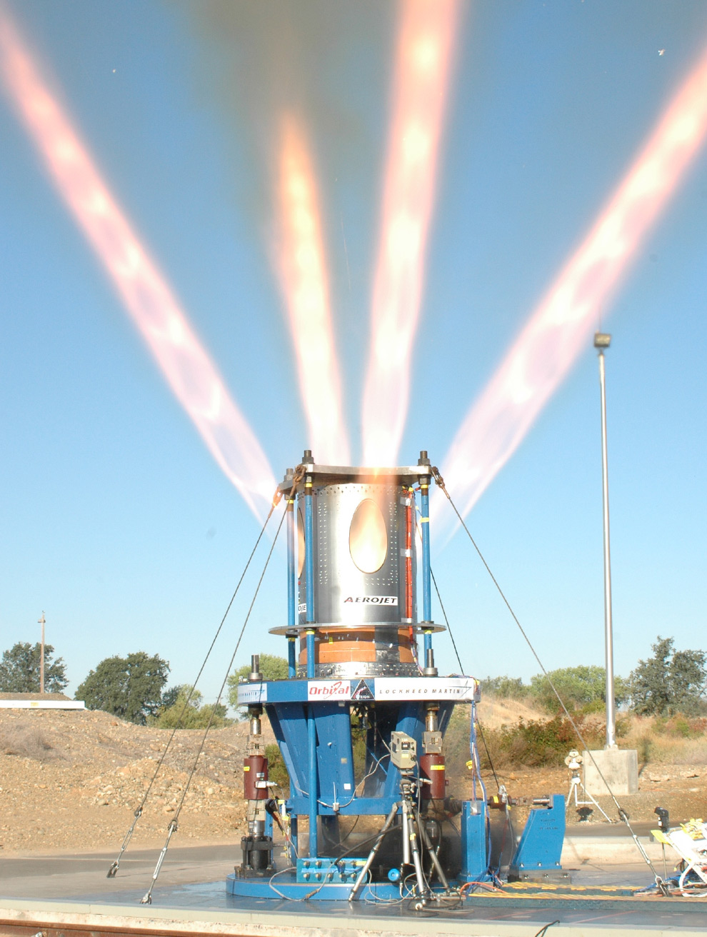
13
A full-scale rocket motor the Orion Crew Module Jettison Motor - fires at the Aerojet facility in Sacramento, Calif on July 18th, 2008. This test will help in the development of NASA's Orion jettison motor that is being designed to separate the spacecraft's launch abort system from the crew module during launch. (Aerojet) #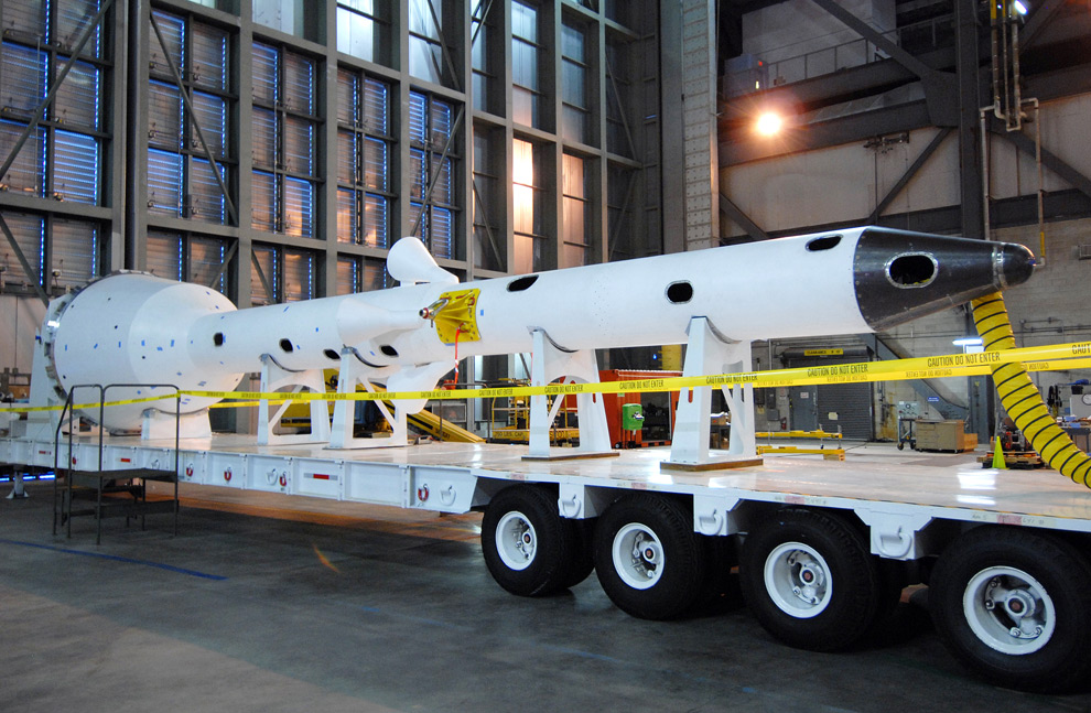
14
The Ares I-X launch abort system that will form the tip of the Ares rocket arrives in the Vehicle Assembly Building at NASA's Kennedy Space Center in Florida on January 31st, 2009. The launch abort system will provide safe evacuation if a launch vehicle failure occurs. (NASA/Jack Pfaller) #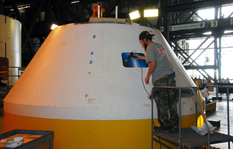
15
In high bay 4 of the Vehicle Assembly Building at NASA's Kennedy Space Center, a worker applies a window decal on the Ares I-X mock-up crew module on February 10th, 2009. When fully developed, the 16-foot diameter crew module will furnish living space and reentry protection for the astronauts. (NASA/Tim Jacobs) #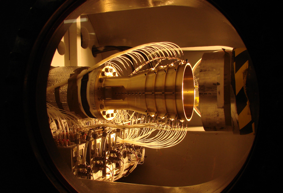
16
"Nozzle side loads" are a major design consideration for rocket engine exhaust nozzles, and the J-2X engine is no exception. Side loads, or pressures exerted on the sides of the engine nozzle, are most severe during engine start as the rocket exhaust plume fills the nozzle, as well as at shutdown when the plume empties from the nozzle, pressing unevenly around the nozzle walls. Testing at the Marshall Center's Nozzle Test Facility enables Pratt & Whitney Rocketdyne design engineers to characterize these side loads and apply this test data to computer analyses used to design the nozzle to withstand the side loads. (Joseph Ruf / NASA/MSFC) #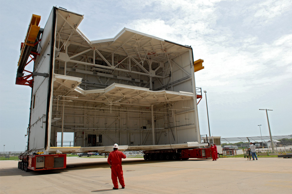
17
Platform C is moved away from the Vehicle Assembly Building at NASA's Kennedy Space Center on June 26th, 2008 to allow refurbishment of the facility for the Constellation Program's Ares 1-X vehicle in high bay 3. The platform will be demolished. (NASA/Amanda Diller) #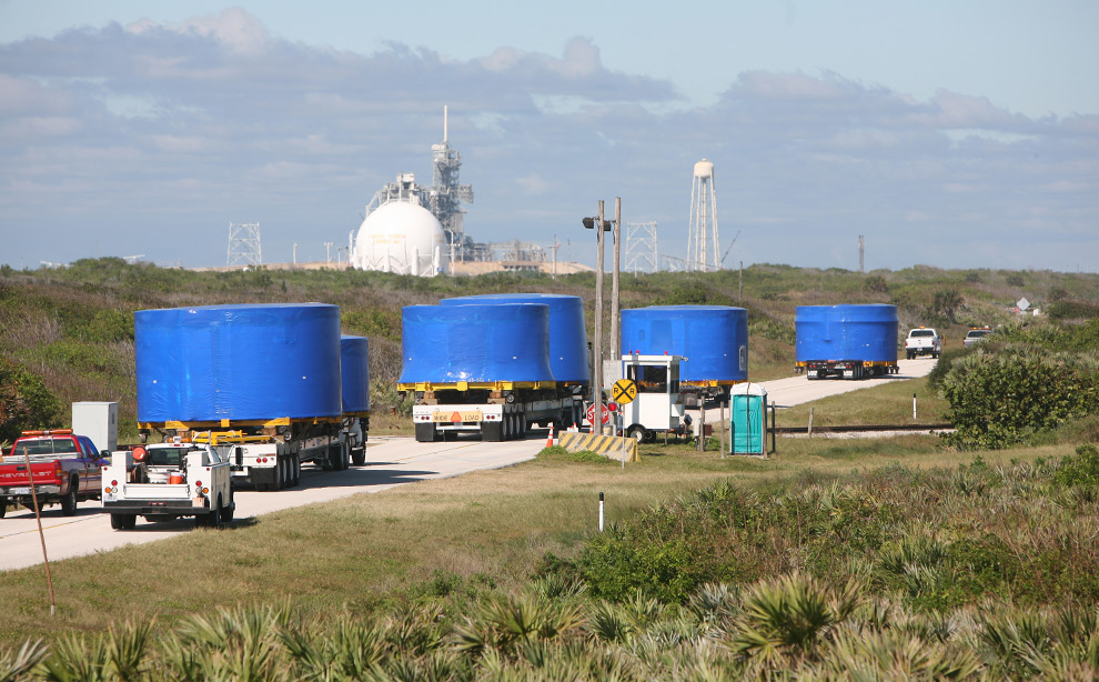
18
A convoy of trucks passes a launch pad as it makes the journey from Port Canaveral to the Vehicle Assembly Building's high bay 4 at NASA's Kennedy Space Center in Florida. The trucks carry Ares I-X upper stage simulator segments, wrapped in blue protective plastic. The simulator comprises 11 segments that are approximately 18 feet in diameter. Most of the segments will be approximately 10 feet high, ranging in weight from 18,000 to 60,000 pounds, for a total of approximately 450,000 pounds. (NASA/Cory Huston) #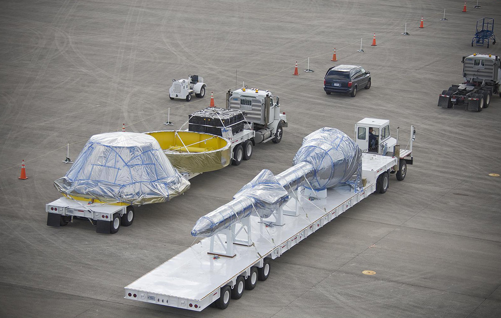
19
Ares I-X simulated crew module and launch abort system flight hardware arrives at NASA's Kennedy Space Center in Florida. This hardware will complete the nose of the rocket. Nearly 150 sensors on the hardware will measure aerodynamic pressure and temperature at the nose of the rocket and contribute to measurements of vehicle acceleration and angle of attack. The data will help NASA understand whether the design is safe and stable in flight. (NASA/Sean Smith) #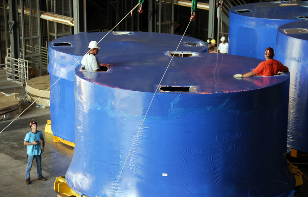
20
Inside the Vehicle Assembly Building's high bay 4 at NASA's Kennedy Space Center in Florida, workers secure the cranes that are being used to offload Ares I-X upper stage simulator segments onto the floor. The segments arrived November 4th at Port Canaveral, Fla., aboard the Delta Mariner. (NASA/Cory Huston) #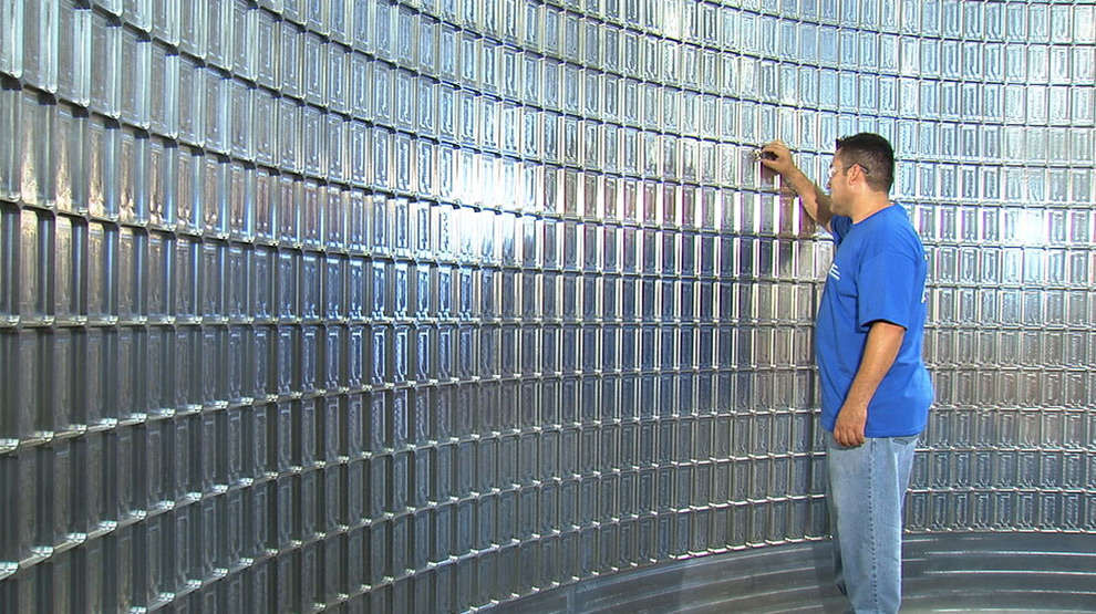
21
This still from an HD video shows an aluminum manufactured panel that will be used for the Ares I upper stage barrel fabrication. (NASA/MFSC) #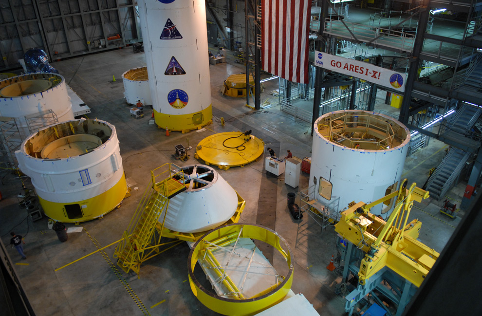
22
In the Vehicle Assembly Building's high bay 4 at NASA's Kennedy Space Center in Florida, the simulator crew module for the Ares I-X rocket joins other rocket segments on the floor prior to further tests and eventual assembly. (NASA/Jack Pfaller) #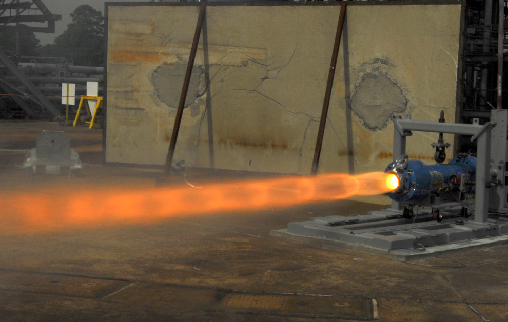
23
Engineers at NASA's Marshall Space Flight Center in Huntsville, Alabama completed first-round testing on Sept. 11, 2008 of a key motor for the next-generation Ares I rocket. The ullage settling motor is a small, solid rocket motor that will assist in vehicle stage separation and provide the forward motion needed to push fuel to the bottom of the fuel tanks during the launch to orbit of the Ares I rocket. (NASA/MSFC) #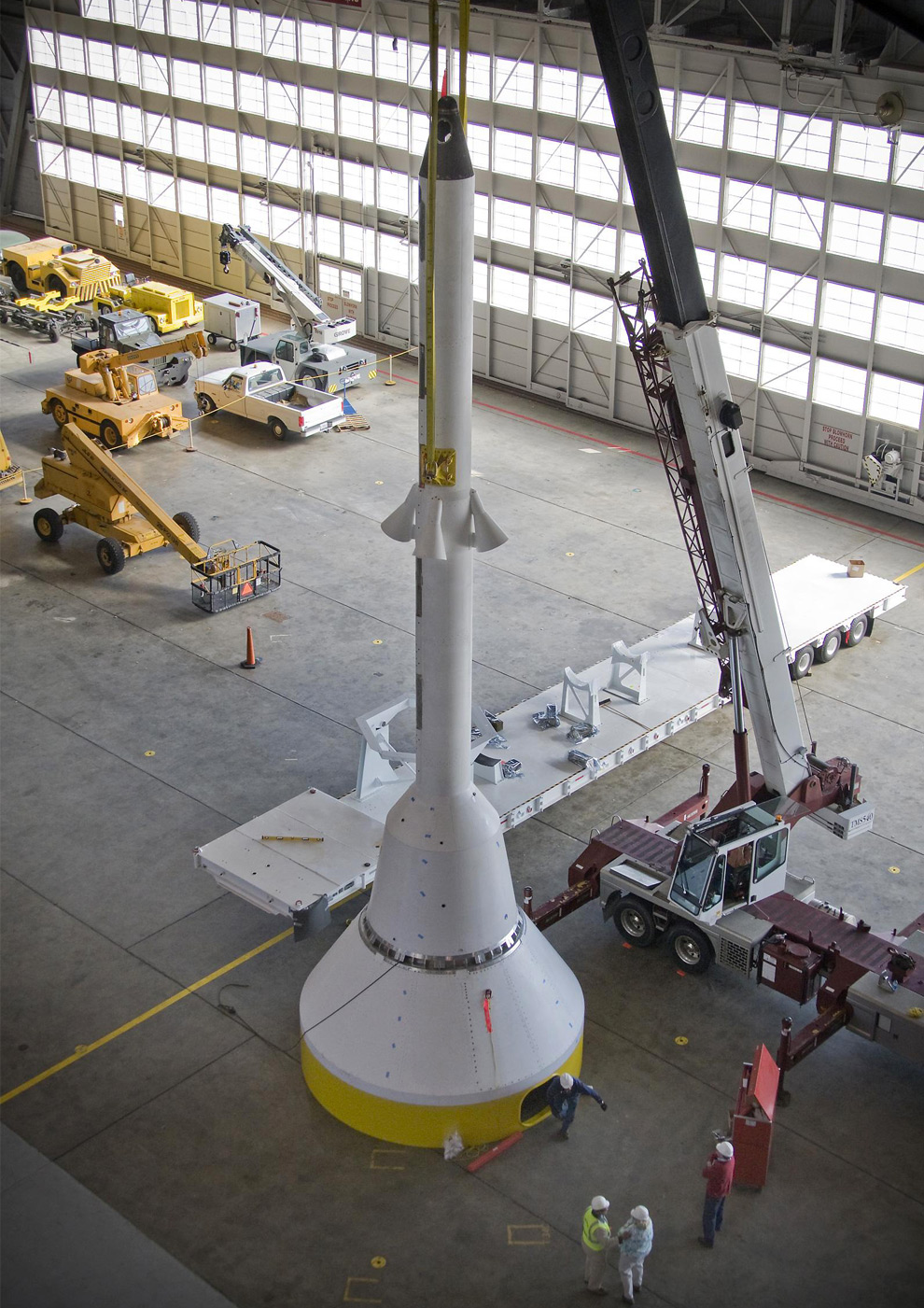
24
An overhead View of Crew Module and Launch Abort System (CM/LAS) Stack for the Ares I-X rocket at NASA's Langley Research Center, in Hampton, Virginia. (NASA/Sean Smith) #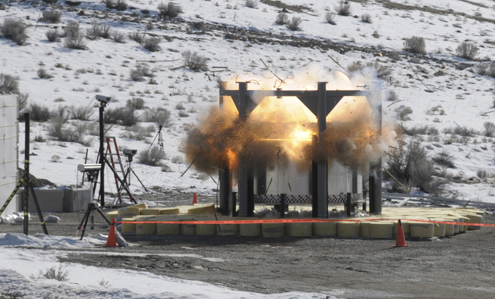
25
A full-scale separation test of the forward skirt extension for the Ares I-X flight test took place on January 30th, 2009 at a facility in Promontory, Utah. (NASA/ATK) #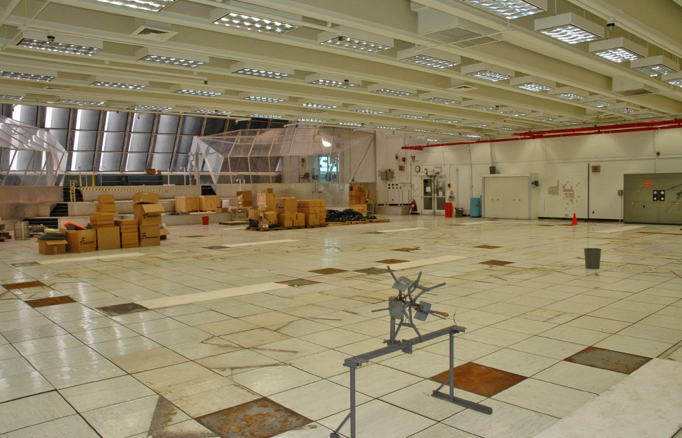
26
Firing Room 1 of the Launch Control Center is shown, stripped of its old equipment in preparation for transforming it to support the launch operations for the Ares launch vehicles. The Shuttle Processing Transition Team has worked to decommission Firing Room 1, also known as FR1, for transfer to the Constellation Program. The transition includes removing all the computer systems currently in the room and installing new equipment, furnishings and software. The room was recently renamed the Young/Crippen Firing Room to honor Commander John Young and Pilot Robert Crippen in tribute to the 25th anniversary of the first space shuttle flight on April 12, 1981.(NASA/Jim Grossmann) #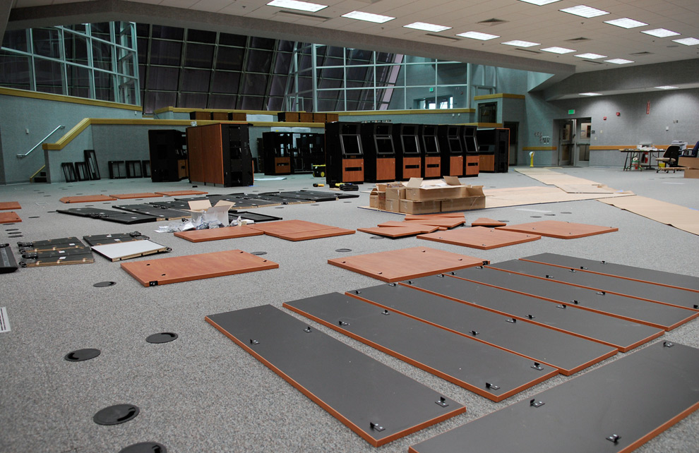
27
In Firing Room No. 1 in the Launch Control Center at NASA's Kennedy Space Center, panels stretch across the floor in preparation for erecting equipment racks on May 1st, 2008. The refurbished firing room will support the future Ares rocket launches as part of the Constellation Program. The Launch Control Center firing room windows face the launch pads. (NASA/Kim Shiflett) #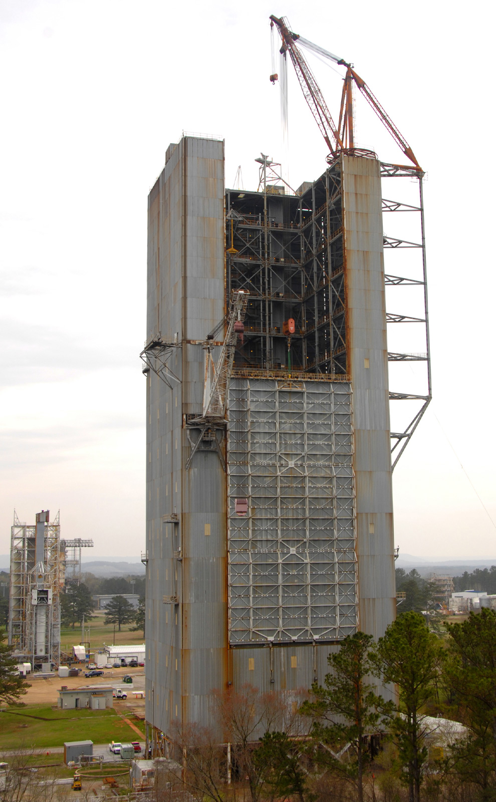
28
Engineers began major refurbishment to the Marshall Center's Dynamic Test Stand in March 2008, removing the roof and lowering the 144-foot-high, 71-ton door. Marshall currently is making safety upgrades to the stand, overhauling the 200-ton derrick crane and installing a new electrical power system, restoring the facility to its Apollo-era capabilities in anticipation of full-scale Ares testing beginning in July 2011. The test program is expected to take approximately one year. (NASA/MSFC) #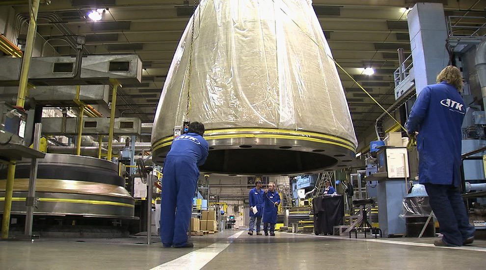
29
Engineers work toward the installation of O-rings in the aft nozzle section in support of the Ares/CLV First Stage on February 15th, 2008 at an ATK facility in Utah. (NASA/MFSC) #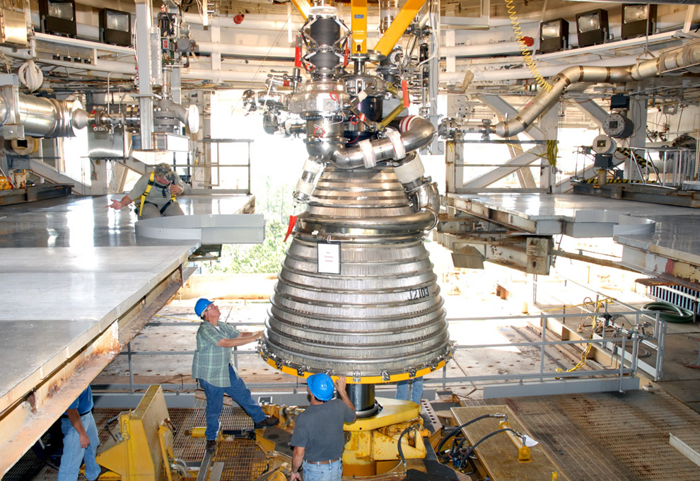
30
Core components of the J-2X engine being designed for NASA's Constellation Program were installed on the A-1 Test Stand at NASA's Stennis Space Center near Bay St. Louis, Mississippi on September 20th, 2007. Tests of the components, known as Powerpack 1A, were conducted from November 2007 through February 2008. The Powerpack 1A test article consists of a gas generator and engine turbopumps originally developed for the Apollo Program that put Americans on the moon in the late 1960s and early 1970s. Engineers are testing these heritage components to obtain data that will help them modify the turbomachinery to meet the higher performance requirements of the Ares I and Ares V launch vehicles. (NASA) #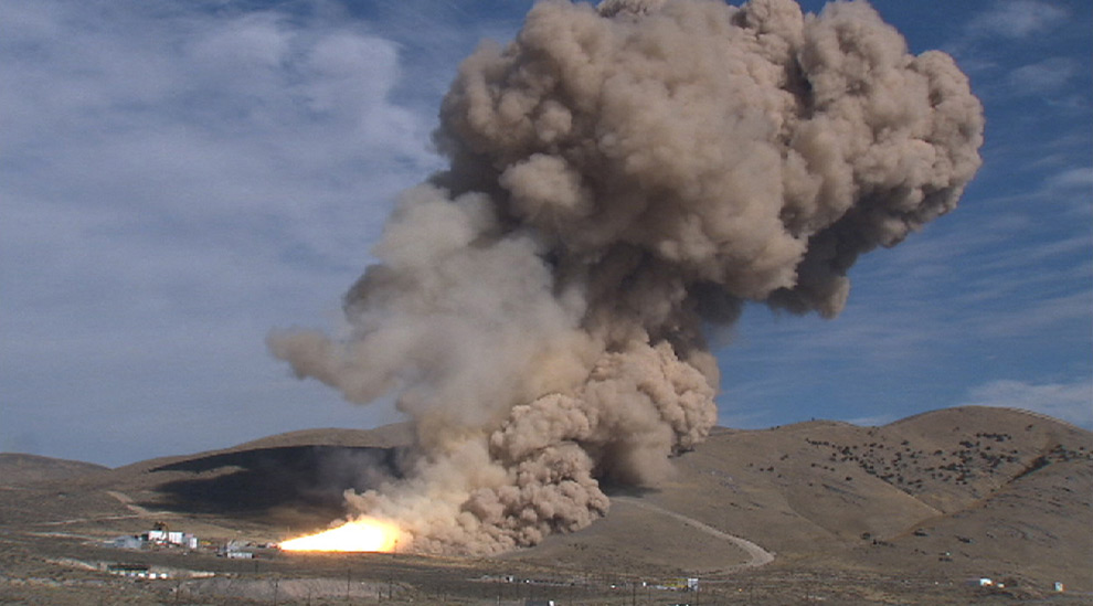


 http://ya-mujeeb.com/
No comments:
Post a Comment
Your feedback is warmly welcomed:
Contac us at: info@pakistanprobe.com